Wednesday, May 30, 2018

First Set Of Wheels


It must be sixty years old, but it's still serviceable. The wheels aren't original -- the original wheels and their bearings went south long ago. It used to have removeable side, front and rear enclosure 'fences' that plugged into steel receptacles, but those are long gone. Anyway, what's left of it is still a useable wagon, and a tangible connection to my long lost boyhood.

I just finished giving its hardwood body an application of Thompson's Water Seal, in hopes of making it last maybe another sixty years.

# # #


# # #

Sunday, May 20, 2018

2009 Hyundai Tucson Rear Wiper Blade


The rear wiper blade on my Tucson is about done like dinner.


It's nominally a 12" blade; actual length is 11 13/16". My son got me a new one from rockauto.com -- an ANCO AR-12X.


Blade replacement is a breeze. Lift the wiper up off the glass and it stays lifted.


Lever out the old blade from its lower end. The blade will pop out of its receptacle once sufficient force is applied. The new blade just snaps into place.

The centre portion of the blade's arm isn't quite symmetrical, but that doesn't seem to matter; the blade goes in either way.

There's a YouTube video that shows blade replacement reasonably well.

# # #


# # #

Saturday, May 19, 2018

Briggs & Stratton Model 95902 Recoil Starter Cog-And-Ball Clutch


I've coined the term 'cog-and-ball' for want of a better name for the clever little clutch in the recoil starter of a Briggs & Stratton Model 95902 vertical shaft lawnmower engine.

This type of clutch is all but trouble free, and likely to last forever. There is a limit, though, to how much neglect it can take, and the one in my old Sears Craftsman 20" mower reached its limit this spring. The clutch still engaged and worked for starting the engine, but upon starting I'd get a dreadful shrieking noise, and the starter's pull-cord would vibrate violently between the handle and the starter housing. I surmised that the cog-and-ball clutch was perhaps binding slightly and causing all the noise, and so I decided to open it up for a look-see.

- - -

First off, the cowl with the recoil cord/pulley has to come off. There are three obvious 1/4"-20 x 1/2" hex head screws that hold it on. A 7/16" socket wrench is needed.


That gets you to where you can get at the screen over the flywheel.


Remove the two screws with a 1/4" nutdriver, and you have access to the clutch's dust cover/seal.


Hold down the centre spindle while you pry up the dust cover with a pocket knife blade, and you get to see inside.


And there we have what I call a 'cog-and-ball' clutch. With the engine stopped, the balls are free to roll down their ramps to where they meet their central cogs. When the starter cord is pulled, the clutch's central cog spindle jams one of six balls up against an outer cog, and so can turn the flywheel. Once the engine starts, centrifugal force sends the balls up their ramps and into their pockets until the engine is stopped.

 The central cog spindle rides on the upper end of the crankshaft, and it must freewheel smoothly without any binding, else you get the noise and vibration effects that I was getting. Clean the spindle's bore and the upper end of the crankshaft. (Mine was fouled with gummy old lubricant.) There's what I take to be a lubricant wick up inside the bore of the cog spindle. Give that a good soaking with WD-40, reassemble the works and you're good to go. Spray some WD-40 around the lip of the clutch cover's seal. Use no grease inside the clutch; nothing must impede the free motion of the balls up and down their ramps.

- - -

Note that the lower/outer portion of the clutch is also the flywheel nut on this engine. To get it off, restrain the flywheel, and crank the clutch portion off in the normal direction with a big pair of Channellocks. Mine came off easily. Here's a view of it removed and off to the side.


# # #


# # #

Thursday, May 17, 2018

2009 Hyundai Tucson 2.0 Litre (4 Cylinder) Engine Oil Change


It's an oil change like most any other oil change. Here's some information that you may find helpful.

Getting Clearance

I haven't even looked into how one might jack the vehicle. I just ramp it, like so.


Drain Plug

The plug is an M14x16mm hex head screw, 17mm A/F (across flats). There's no o-ring seal -- just a flat integral washer. Here's a view of the plug.


The plug is easy to spot at the rear of the sump.


Oil Filter Access

There's a plastic panel across the front of the vehicle that hinders access to the oil filter.


It's possible to change the oil filter without removing the plastic panel, but I advise against doing that. When you remove the oil filter, quite a bit of oil drools out, and makes an awful mess on top of the panel if the panel is in place.

The panel is not difficult to remove, and removing it makes for a much neater job. There are six obvious M8x25mm hex head screws that fasten the panel. The hex heads are 12mm A/F.

When reinstalling the panel, take care to get the panel's front edge up above the lower rear edge of the front bumper shroud. Use an anti-seize compound on the M8 screws, and you'll have an easier time of removing the panel come the next oil change.

With the plastic panel out of the way, you have full access to the oil filter where it resides just below the alternator.


The filter is about 3" diameter x about 3" tall.


Canadian Tire P/N is 017-1899-8. Fram P/N is PH9688.

Oil

Capacity with filter change is 4.0 litres. Hyundai recommends 5W-20 or 5W-30; 10W-30 for temperatures above zero Fahrenheit (-18 Celsius). Since the temperature where I live rarely goes below zero Fahrenheit, I've been using 10W-30.

# # #


# # #

Thursday, May 10, 2018

A Spark Generating Apparatus


I'm working on developing an Arduino-based small engine tachometer that takes its input signal from an engine's spark plug wire. Going outside to experiment with a live engine got tiresome, so I arranged this on my wood lathe.


It's a scrapped Tecumseh TVS90 lawnmower engine with the fuel tank, air cleaner and carburetor removed.

It works. I run it at the lathe's lowest speed (500 rpm) and I get spark generation for testing my tachometer design. A downside is that crankcase oil seeps down past the piston eventually and comes out the open spark plug hole in the cylinder head. I'm also getting what I take to be electromagnetic field generation from the ignition coil that's overwhelming my pickup probe. I haven't had that problem with a live engine mounted on a lawnmower.

So, it remains to be seen whether or not I can call this item a success.

- - -

Addendum -- SATURDAY, FEBRUARY 9, 2019

Here's a brief video of the rig in action.


# # #


# # #

Tuesday, May 8, 2018

An Arduino Small Engine Tachometer


I've been casting about for an Arduino sketch for a tachometer that I could adapt to small engines. The most promising one I've found so far is this one from "https://playground.arduino.cc/Learning/Tachometer". Here's the complete code if you'd rather not follow the link.

- - -

//
// This example shows one way of creating an optoswitch
// using an IR LED as emiter and an IR LED receiver as
// light sensor.
// On this case it acts as a tachometer to count the
// revolutions per second of an aeromodelism plane's
// propeller.
//
//           + GROUND                    +GROUND         
//           |                                        | 
//           <                                        <
//           > 220 ohm resistor             > 220 omh resistor
//           <                                        <     
//           |                                        | 
//           |                                        |
//         -----                                    -----
//          / \    >>IR LED emiter >>  / \   IR LED receiver
//         -----                                    -----
//           |                                        |
//           |                                        |
//           + +5VCD                        +  ANALOG INPUT 0
//


int val;
long last=0;
int stat=LOW;
int stat2;
int contar=0;

int sens=75;  // this value indicates the limit reading between dark and light,
              // it has to be tested as it may change acording on the
              // distance the leds are placed.
int nPalas=2; // the number of blades of the propeller

int milisegundos=500; // the time it takes each reading
void setup()
{
  Serial.begin(9600);
  pinMode(13,OUTPUT);
}

void loop()
{
  val=analogRead(0);
  if(val<sens)
    stat=LOW;
   else
    stat=HIGH;
   digitalWrite(13,stat); //as iR light is invisible for us, the led on pin 13
                          //indicate the state of the circuit.

   if(stat2!=stat){  //counts when the state change, thats from (dark to light) or
                     //from (light to dark), remmember that IR light is invisible for us.
     contar++;
     stat2=stat;
   }
   if(millis()-last>=milisegundos){
     double rps=((double)contar/nPalas)/2.0*1000.0/milisegundos;
     double rpm=((double)contar/nPalas)/2.0*60000.0/(milisegundos);
     Serial.print((contar/2.0));Serial.print("  RPS ");Serial.print(rps);
     Serial.print(" RPM");Serial.print(rpm);Serial.print("  VAL ");Serial.println(val);
     contar=0;
     last=millis();
   }
}

- - -

The sketch was evidently developed by a Spanish speaker for timing a model airplane propeller. Several things needed changing for my purposes:
  • I wanted a digital, not an analogue, input.
  • The tachometer needed to 'see' one event per revolution.
  • I wanted an LCD output in addition to the serial output.
After some tinkering, I came up with this:

- - -

#include<LiquidCrystal.h>
LiquidCrystal lcd(12, 11, 5, 4, 3, 2);
int val;
long last=0;
int stat=LOW;
int stat2;
int contar=0;

//int sens=75;
int sens=500;// this value indicates the limit reading between dark and light,
//int sens=200;              // it has to be tested as it may change acording on the
              // distance the leds are placed.
int nPalas=1; // the number of blades of the propeller

int milisegundos=1000; // the time it takes each reading
void setup()
{
  Serial.begin(9600);
  pinMode(6,INPUT);
  pinMode(13,OUTPUT);
}

void loop()
{
  //val=analogRead(0);
  val=digitalRead(6);
  //if(val<sens)
  if(val==0)
  stat=LOW;
  else
   stat=HIGH;
   digitalWrite(13,stat); //as iR light is invisible for us, the led on pin 13
                          //indicate the state of the circuit.

  if(stat2!=stat){  //counts when the state change, thats from (dark to light) or
                     //from (light to dark), remmember that IR light is invisible for us.
     contar++;
   stat2=stat;
   }
   if(millis()-last>=milisegundos){
     int rps=(contar/nPalas)/2.0*1000.0/milisegundos;
     int rpm=(contar/nPalas)/2.0*60000.0/(milisegundos);
     Serial.print((contar/2.0));Serial.print("  RPS ");Serial.print(rps);
     Serial.print(" RPM");Serial.print(rpm);Serial.print("  VAL ");Serial.println(val);
     //lcd.clear();
     lcd.begin(16,2);
     lcd.print("RPS or Hz=");
     lcd.print(rps);
     lcd.setCursor(0,1);
     lcd.print("RPM=");
     lcd.print(rpm);
     contar=0;
     last=millis();
   }

}

- - -

'Tinkering' is the operative word. I'm pretty clueless where Arduino code is concerned. An expert would no doubt find plenty wrong with what I've done, but it appears to work. It got me to where I could experiment with spark plug wire pickups, and come up with a working small engine tachometer.

- - -

Getting A Signal Off A Spark Plug Wire -- THURSDAY, MAY 10, 2018

Here's what I came up with for a spark sampling circuit.


And here's a view of C1 and L1.


The inductor is from a set that I got from Amazon. The capacitor is a crude thing that I made out of two pieces of beer can aluminum and double-sided tape; it's about one inch square. (I later replaced that homemade capacitor with a 33pF disc capacitor, and that works about as well.)

In use, a pickup is simply held next to an engine's spark plug wire. Either pickup works about equally well to coax a useable signal, ¬SPARK, out of Q1. That signal is messy, though. It turns out that a small engine spark is not a single event -- it's a little sequence of events. The ¬SPARK signal cannot be applied directly to an Arduino as an input; an erratic, chaotic rpm reading will result. To get around that, I applied the ¬SPARK signal to a 555 timer configured in its monostable mode.

- - -

Conditioning/Digitizing The ¬SPARK Signal -- FRIDAY, MAY 11, 2018

Here's the schematic for the 555 timer circuit that turns the messy ¬SPARK signal into a tidy pulse.


And here's the Arduino wiring for the display.


So there we have all the elements of my tachometer prototype, should you wish to recreate it. Here's a view of the prototype at work on the bench.


The business to the right of the display is a bit of known frequency input circuitry for test purposes. I'll post the schematic for that and an explanation shortly.

- - -

A Tachometer 'Speed' Signal Generator -- SATURDAY, MAY 12, 2018

For bench testing my tachometer prototype, I needed a signal source that would give me a known 'speed' input to the spark sampling transistor, Q1 in the first schematic above. A 60 Hz signal works out to 3600 rpm, and a 120 Hz signal works out to 7200 rpm, so I put together the half-wave and full-wave rectifiers shown below.


In use, VR1 and VR2 are adjusted so that Q1 is just triggered into putting out a ¬SPARK signal. The desired signal, 3600 'RPM' or 7200 'RPM' is applied via a breadboard jumper wire.

- - -

Spark Generation In The Workshop -- SUNDAY, MAY 13, 2018

This post describes an apparatus that lets me bench test the tachometer with a live spark.

- - -

Packaging And Refinement

I needed a steel enclosure for the tachometer, and given the cost of those things and the hassle to obtain one, I went to the dollar store to see what I might find. For $4.00, I came up with this.


It's an enameled steel storage tin. It's 5 1/2" x 5 1/2" x 4 1/8" tall, which is a bit large for what's needed, but at least it won't be cramped inside. The picture shows it with a 16 x 2 LCD installed in the tin's lid. Here's a rear view.


There's an on/off switch, a reset push-button and a 1/4" phone jack for a probe. I've added screws for securing the cover. Here's a look inside.


I still have wiring to finish up properly, and that 9V rectangular battery needs to be replaced by a cell holder that will give me a 6 x AA cell battery.

- - -

Accuracy -- TUESDAY, MAY 15, 2018

Accuracy is not great, but it's not bad either.

With a known 3600 rpm input, the readout ranges from 3600 to 3630; that's within 1%. I think the reason for the variation is that the one-second measurement 'window' and the read pulse train are not synchronized -- the device may drop or pick up a half or a full cycle now and then. Accuracy worsens considerably at low speeds. With a known input very near to 500 rpm, the readout ranges from 480 to 540; that's within 8%. I imagine that it should be possible to synchronize the measurement window with the read pulse train, but doing so may well be beyond my capability.

Susceptibility To Engines' EM Fields

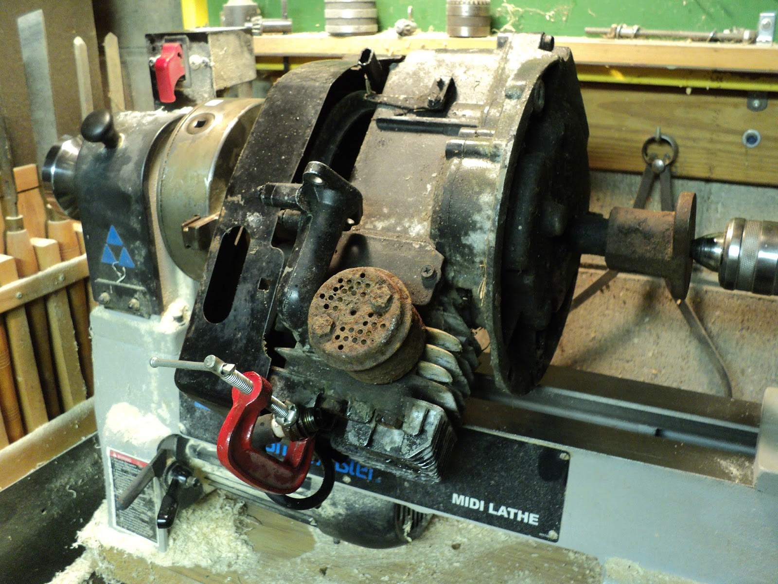
With a steel-shrouded engine mounted on a steel mower deck, the probe needs to be very near the spark plug wire to pick up a signal. With my lathe-mounted spark generating apparatus, the tachometer gets an input signal even with the probe at some distance from the spark plug wire. The same is true of a scooter engine that I have. The scooter engine's shroud is a cast, non-ferrous alloy, and the ignition system seems to radiate a considerable EMF.

Anyway, there's my small engine tachometer, for whatever it's worth. I guess I can call it a qualified success.

- - -

Update -- THURSDAY, MAY 16, 2019

I've given the instrument a proper battery pack -- a six 'AA' cell holder.


I tried this for a pickup.


It's a 5 1/2 foot length of light gauge shielded wire with a battery terminal post alligator clip on the end. The clip connects directly to the instrument's input point via the shielded wire. The shield braid connects to signal/chassis ground at the 1/4" phone plug. In use, the alligator clip is simply clamped onto a spark plug wire's insulation.

It's not entirely free of flakiness, but it works well enough for things like setting governed speed on a lawn mower engine.

# # #


# # #

Tecumseh TVS90 Carburetor Removal


This old brute of a lawnmower spent the winter outside with fuel left in it. It starts, but there may God-knows-what-all sort of muck in the carburetor. So, in the interest of a trouble-free mowing season, I'll take the carb off and dismantle and clean it. I'll also remove the fuel tank, and exchange it for one I have that's clean and dry inside


I've posted about TVS90 carburetor maintenance before, but I didn't write up the removal procedure, so here goes.

- - -

Tools needed are nutdrivers and combination wrenches in sizes 1/4", 5/16", 3/8" and 7/16".

The pictured lawnmower has an operator's engine speed control lever. That complicates carburetor removal a bit because of a governor/throttle-linkage plate that must come off.

Fuel Tank

The fuel line tubing is 5/16" I.D., secured with a spring-type hose clamp. Lever the tubing off of the fuel tank's discharge nipple.


Hold a fingertip over the open end of the nipple while you lift the tank up off its keepers at the rear of the engine cowl. It's helpful to have a salvaged automotive engine vacuum port cap on hand, so you can safely set aside the fuel tank.


And here's a view of the rear of the engine cowl with the fuel tank removed.


Note the channels that are the fuel tank's keepers.

Throttle Cable

Note the position of the cable jacket at its clamp. Loosen off the clamp and unhook the cable end from its lever.


Air Cleaner

Pry up the air cleaner's lid and remove it.


Two screws fasten the air cleaner's body to the carburetor's intake flange -- remove those and the air cleaner is free to come away.


One of the two screws is rather concealed at the inboard side of the air cleaner's output horn. With the air cleaner removed, note the nipple that connects to the crankcase ventilation tube. At reinstallation, take care to remake that connection as you get the air cleaner in place.

Here's a view of the air cleaner's output horn. Note the square cross-section o-ring seal that resides in a circular notch.


With the air cleaner off, you can see the governor/throttle-linkage plate that resides over top of the carburetor.


You have to remove the engine's cowl before you can get that plate off. Cowl removal is straightforward; there are two screws at the front of it and two screws at the rear of it. There's a fifth screw that fastens the oil filler tube to the cowl. The oil filler tube may tend to tumble once it's unfastened. Set it aside and take care not to let foreign matter get into the tube's hole to the sump while the tube is off.

With the cowl removed, you have clear access to the governor/throttle-linkage plate.


Note the following:
  • The mower's engine speed lever does not operate the throttle directly. The lever acts on the governor spring, so as to alter governed engine speed.
  • There's a single kill wire to be disconnected at the front of the plate.
  • The throttle link attaches to the uppermost hole in the governor arm.
  • The governor spring attaches to the next hole down in the governor arm. The spring's link attaches to the plate's engine speed lever.
  • The plate is attached to the top of the intake pipe by two screws in elongated holes. Evidently, the position of the plate is adjustable -- I have no idea why. Note the plate's position and be sure to get it back the same way at re-installation.
With the governor/throttle-linkage plate removed, you're ready to remove the carburetor from the intake pipe.


The fasteners are two 1/4"-28 screws with nuts. The inboard screw and its nut are a bit awkward to deal with. When you get the carburetor off, note the gasket that goes between the carburetor and the intake pipe. As long as that gasket is undamaged, it's reuseable. Replace it if in doubt about its condition -- that gasket is important.

And there we are, at the point where the carburetor can be opened up and its innards attended to.

# # #


# # #

Saturday, May 5, 2018

Beware Of Fake Crimp Connections


Some cheap electrical connection goods, like the 20" alligator clip jumper lead pictured below, make use of a species of 'crimp' connection that's scarcely fit to be called a 'connection'.


The bared end of a wire is simply folded back onto its insulation. The wire end is laid into a receiving channel, and the channel is squeezed closed over the works.


The connection attained that way is iffy at best. Flakiness and outright openess are not uncommon. The only fix is to open up the 'crimp' with a fine sidecutter (as I've done in the photo above), make a soldered connection and re-close the 'crimp'.


I had one of these connection types give me the gears on a small engine recently. The connection was in a bullet-style pin for the kill switch circuit. It went open and the engine couldn't be switched off. Soldering the connection fixed that trouble.


If a piece of electrical gear has such connections in it and it's behaving erratically, odds are good that it's a fake crimp connection that's at fault.

- - -

Update -- FRIDAY, MARCH 15, 2019

Here's an improvement to the alligator clip leads -- add a one inch length of 2mm or 3/32" heat shrink tubing to the wire right where it meets the alligator clip.


One ends up with a nicely strain-relieved lead end.


# # #


# # #

Wednesday, May 2, 2018

A Battery Tester From Amazon


I got this pretty much as a lark. I thought it might help me find Ni-Cd cells that were taking on a fake charge.


It's an 'AMPROBE'[1] BAT-200 Battery Tester.

For $5.99 CDN I figured it might at least be cheap entertainment for a while.

There's not much to it; here are two views of its innards.


There's a meter, and a tiny printed circuit assembly with four resistors on it. I tried it out on a variety of cells and 9V batteries, and I decided that it's not a bad little instrument; it's quite well thought out.

There's a chart on the back of it that makes it pretty clear what the unit is up to.


For 1.5V cells, the tester puts a 4 ohm load across the cell and reads out cell terminal voltage under that load. (375mA nominal.) A terminal voltage above 1.0V is a 'good' indication; a terminal voltage below 0.9V is a 'bad' indication. Similarly, for 9V batteries, the tester puts a 215 ohm load across the battery and reads out battery terminal voltage under that load. (42mA nominal.) A terminal voltage above 6.5V is a 'good' indication; a terminal voltage below 5.3V is a 'bad' indication.

Those test loads are reasonable, and they give a reasonable indication of cell/battery condition.

So, the item is not a gimmick. It really is what it says it is.

- - -

NOTE:

[1] The Chinese manufacturer is doing a shameless bit of brand name piracy there. Amprobe is an American manufacturer of high-end electrical instruments. There's no way that this little tester is an Amprobe product.

# # #


# # #