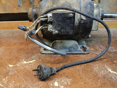
I got this old brute of a 1/2 hp motor along with an 8" table saw some time ago.
The story of the 8" table saw is here. The saw got sold; this motor stayed behind. It's big and heavy for 1/2 hp. It would be suitable for powering a wood lathe. I have no foreseeable use for it, so I figure I may as well refurbish the thing, and possibly sell it.
So, here goes a leisurely teardown and paint job. It should be quite a handsome old beast when I get done with it.
The Pulley
I may need to use a puller to get that 3" diameter, 1/2" V-belt pulley off the rusty 3/4" diameter shaft.
This setup should do the job.
That worked well enough for getting the pulley to move on the shaft, and freeing up the key so it could be removed, but there's a snag -- the end of the shaft is mushroomed a bit.
The pulley won't come off until I've done away with that mushrooming. I'll do that with a mill file with the motor running as its own 'lathe'.
- - -
And here we are with the shaft dressed, the 3/16" key straightened and filed so it's a sliding fit and the pulley cleaned.
The pulley is embossed, "CONGRESS TOOL & DIE CO. DETROIT - U.S.A. 3-A"
There's quite an interesting video about that firm here.
Congress appears to still exist as a manufacturer of pulleys.
The Wiring
Hmmm. That's about as hideous as it ever gets. I can see why the wiring was brought outside of its box -- that box is pretty small, and must make for a cramped set of connections. However, it's not right, and I must try to get it together as it ought to be, with the connections enclosed.
It appears that the wires' identifying labels are long lost, so the following photo will have to serve as a 'diagram' for the 110 volt winding connections.
The 220 volt configuration is anybody's guess. It would have to be worked out by trial-and-error were it wanted.
- - -
And lo and behold, the wires' identifiers aren't lost after all. They're the brass coloured bands in the following photo.
I'll trim the ends of those leads, and strip and tin them so they'll be fit for connection with setscrew-type wire connectors.
The Start Capacitor
It's quite the piece of construction.
It's probably best if I don't unwrap it, if I ever mean to get it back together again.
A Mystery Compartment
I wonder what this is all about.
Let's take a look.
There's a board with two terminals with wires attached. I wonder if this is for rotation direction reversal. I'll have to try that out. There's nothing pasted on the inner surface of the compartment's cover to inform me what it's for.
- - -
Reversibility it is. Swap the positions of the two wires, and direction of rotation is changed.
- - -
The Output End Bell
The motor is held together with four 1/4"-20 x 6 3/8" thru-bolts with 7/16" A/F hex nuts.
It appears that provision was built into the bell to ease removal of it. There's a recess on either side for a chisel tip, to aid in knocking the bell off its seat.
And here we are with the bell off and the rotor out.
The sleeve bearing in that bell has a bit of slop to it. I gauged it to be about 0.0065". It's in the vertical direction, which is consistent with how the motor was installed on the old saw that it came with. The motor was directly underneath the saw, with a crude motor mount that probably made for an overly tensioned belt.Consequently, the bearing would have tended to wear in the vertical direction. When I've run the motor, I've not seen or heard any evidence that that amount of bearing slop is detrimental.
The amount of sawdust on and in the motor is phenomenal. It will take some doing to get all of its components clean and paint-ready.
The Wiring End Bell
I knocked that off from inside with the aid of a big brass punch. The start capacitor's leads have to be extracted from a tight-fitting grommet in order to free the bell completely.
That bell is missing its capped oiler. I have no idea where to get replacements. I've searched, and come up with nothing. I'll see if I can fit the hole that the oiler was in with a screw for a plug.
The Base
The base is held on by four 3/8"-16 x 3/4" screws w/split lockwashers. Note that the base is not symmetrical end-to-end.
Painting Begun
With a lot of compressed air, I got the centre frame portion of the motor clean of sawdust, and I cleaned the part's exterior with lacquer thinner.
Spray painting the part would have been ideal, but masking the windings inside looked like an awkward, iffy bit of business, so I went with brush painting. Here's a view of the outcome of that.
That's one coat of Tremclad grey primer, plus two coats of Tremclad gloss black. There are, of course, brush marks evident, but it will do. It's a big improvement on how it was.
The remaining components can all be spray painted. I'll be back when I have that done and the motor reassembled.
# # #
FEEDBACK
# # #


No comments:
Post a Comment