Friday, June 30, 2017

A Small Woodshed


Our home has a fireplace of sorts. It's an old acorn style, like so.


As I understand it, acorn fireplaces are long out of fashion. They're inefficient. Still and all, it is a fireplace, and a fire in it on a winter evening is a very pleasant thing indeed. And in a pinch like an extended power outage the thing could be salvation, in spite of its inefficiency, provided that there's an adequate supply of firewood on hand. So, I thought it wise to finally get around to constructing a woodshed.

I looked around for suitable woodshed plans on the internet, and found an article that pictured a beautiful design. I really like the looks of the woodshed pictured in that article.


That's a beauty, but the article is a bit of a fraud. The plan given in the article is for a shed that's nothing like the pictured one. Emailing the article's publisher about it got me nowhere, so I set about working out a plan myself. That's been an interesting and challenging exercise that's left me in awe of those who can design and build wood structures.

I've managed to draw up the beginnings of a plan for a shed that will resemble the item pictured above. I have enough of a plan drawn up for me to get started on construction, but I don't know enough about construction carpentry to draw up a plan with every last detail in it. So, beyond the initial floor and wall framing, I'll have to make it up as I go along. We'll see how this works out.

My shed will have a 2' by 6' footprint, and stand about 4 1/2' tall at the peak of its roof. Here's a view of the floor foundation completed.


The two skids are 4" x 4" MCA pressure-treated wood. They're to be the only pressure-treated parts of the shed -- I think that pressure-treated wood is way overused.

The framing is 2" x 4" SPF (spruce/pine/fir), held together with No. 8 x 3" deck screws. To attach the framing to the skids, I splurged and got Kreg's HD pocket screw jig. Here's a view of that item at work.


I've long been intrigued by Kreg's pocket screw gear, and this was my excuse to finally acquire some and try it out. I'm impressed. The gear works as advertised. With No. 14 x 2 1/2" screws installed, that woodshed floor foundation is a very sturdy construction.

Flooring

The flooring is 1" x 4" SPF planks, spaced 1/2" apart so there can be some air circulation up through the shed from below. The planks are nailed down with 1 1/2" common spiral hot galvanized nails.


Rear Wall Framing


That framing is all 2" x 3" SPF, held together with No. 8 x 3" deck screws. I expect to be using that size and style of screw extensively throughout the construction of the shed.

Side Walls Framed


Front Framing Less Corner Braces


That centre post is the two off-cuts from the skids. I joined them end-to-end with biscuits and Gorilla Glue to make a long-enough piece for that post. I also used that method to salvage some 2" x 3" off-cuts for studs, as in the following photo.


Doing that saves considerable waste.

Rafters And Front Corner Bracing Installed


Cross-Bracing Installed


I added that cross-bracing because I've decided to go with vertically arrayed board-and-batten siding.

Siding Begun

Here's the first vertical board in place.


That board clamped along the bottom gives me a registration edge for the bottom ends of the siding boards. Then it's easy to mark a board's upper end to agree with the roof line, and cut it with a hand saw just like a real carpenter would. It should look pretty decent when it's all done. I used 1 1/2" hot galvanized spiral finishing nails to attach the vertical board. I wouldn't mind having an air nailer for this, but that's something I've yet to acquire.

Siding Progress

Here's one end of the shed fully sided, with a few battens installed.


The battens are about 7/32" x 3/4" that I ripped from 1" nominal stock. I've attached the battens with 5/8" brads from an Arrow electric stapler. The stapler is just barely up to the task -- I've had to hammer most of the brads to fully seat them.

I carried the siding around the front corner by 1 1/4" for the sake of a more finished appearance.


That's as far as I want to go for a corner treatment.

One Side Fully Battened


Fully Sided


Front Fascia Board

Here's the clamp-up I rigged to allow me to install the front fascia board without assistance.


And here we are with the front fascia board fastened in place with No. 8 x 2 1/2" deck screws.


Next up is the rear fascia board, then the roofing planks.

- - -

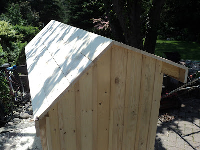
Roof Planked And Both Fascia Boards Installed


Now I have to finish off the gable ends with bargeboards. That will be a bit of a challenge. I have quite a few 1" x 6" off-cuts left to me from the backside and roofing planks. I may make up some bargeboard material from those by biscuit-joining off-cuts together to make long enough boards.

Bargeboards Installed -- SATURDAY, JULY 8, 2017


The most mentally taxing work I've ever done in my life. There were three different angles that had to be discovered, and then expressed with the table saw's mitre gauge. One is constantly doing the mental gyrations necessary to keep it straight in one's head the position and orientation of each angled saw cut. Mistakes could easily be made, and would be costly in ruined material.

Anyway, that's over and done with, and I was able to salvage some off-cuts into the deal.

Drip Edges Installed


The drip edge material is Amerimax No. 3715419 from the Home Depot. I just installed it according to what seemed right to me. Information in this 'information age' can be hard to come by and sketchy. Anyway, that should do what it's supposed to -- keep water from wicking back between the shingles and the substrate.

Roof Shingled -- TUESDAY, JULY 11, 2017


In the above photo, the roof is just awaiting its ridge cap. The shingles are GAF MARQUIS WeatherMax 3-tab, charcoal colour from the Home Depot. Only one bundle was needed to do the entire roof.

Done And In Position -- WEDNESDAY, JULY 12, 2017


I gave the outside and the floor one application of Thompson's Water Seal. Now the shed can peacefully stand where it is and weather, and test out my assertion that pressure treated wood is way overused.

# # #


# # #


Tuesday, June 27, 2017

A General Electric Model 11F801D Motor


I got this old brute of a 1/2 hp motor along with an 8" table saw some time ago.


The story of the 8" table saw is here. The saw got sold; this motor stayed behind. It's big and heavy for 1/2 hp. It would be suitable for powering a wood lathe. I have no foreseeable use for it, so I figure I may as well refurbish the thing, and possibly sell it.

So, here goes a leisurely teardown and paint job. It should be quite a handsome old beast when I get done with it.

The Pulley

I may need to use a puller to get that 3" diameter, 1/2" V-belt pulley off the rusty 3/4" diameter shaft.


This setup should do the job.


That worked well enough for getting the pulley to move on the shaft, and freeing up the key so it could be removed, but there's a snag -- the end of the shaft is mushroomed a bit.


The pulley won't come off until I've done away with that mushrooming. I'll do that with a mill file with the motor running as its own 'lathe'.

- - -

And here we are with the shaft dressed, the 3/16" key straightened and filed so it's a sliding fit and the pulley cleaned.


The pulley is embossed, "CONGRESS TOOL & DIE CO. DETROIT - U.S.A.        3-A"

There's quite an interesting video about that firm here.

Congress appears to still exist as a manufacturer of pulleys.

The Wiring


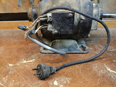
Hmmm. That's about as hideous as it ever gets. I can see why the wiring was brought outside of its box -- that box is pretty small, and must make for a cramped set of connections. However, it's not right, and I must try to get it together as it ought to be, with the connections enclosed.

It appears that the wires' identifying labels are long lost, so the following photo will have to serve as a 'diagram' for the 110 volt winding connections.


The 220 volt configuration is anybody's guess. It would have to be worked out by trial-and-error were it wanted.

- - -

And lo and behold, the wires' identifiers aren't lost after all. They're the brass coloured bands in the following photo.


I'll trim the ends of those leads, and strip and tin them so they'll be fit for connection with setscrew-type wire connectors.

The Start Capacitor

It's quite the piece of construction.


It's probably best if I don't unwrap it, if I ever mean to get it back together again.

A Mystery Compartment

I wonder what this is all about.


Let's take a look.


There's a board with two terminals with wires attached. I wonder if this is for rotation direction reversal. I'll have to try that out. There's nothing pasted on the inner surface of the compartment's cover to inform me what it's for.

- - -

Reversibility it is. Swap the positions of the two wires, and direction of rotation is changed.

- - -

The Output End Bell

The motor is held together with four 1/4"-20 x 6 3/8" thru-bolts with 7/16" A/F hex nuts.


It appears that provision was built into the bell to ease removal of it. There's a recess on either side for a chisel tip, to aid in knocking the bell off its seat.


And here we are with the bell off and the rotor out.


The sleeve bearing in that bell has a bit of slop to it. I gauged it to be about 0.0065". It's in the vertical direction, which is consistent with how the motor was installed on the old saw that it came with. The motor was directly underneath the saw, with a crude motor mount that probably made for an overly tensioned belt.Consequently, the bearing would have tended to wear in the vertical direction. When I've run the motor, I've not seen or heard any evidence that that amount of bearing slop is detrimental.

The amount of sawdust on and in the motor is phenomenal. It will take some doing to get all of its components clean and paint-ready.

The Wiring End Bell


I knocked that off from inside with the aid of a big brass punch. The start capacitor's leads have to be extracted from a tight-fitting grommet in order to free the bell completely.

That bell is missing its capped oiler. I have no idea where to get replacements. I've searched, and come up with nothing. I'll see if I can fit the hole that the oiler was in with a screw for a plug.

The Base


The base is held on by four 3/8"-16 x 3/4" screws w/split lockwashers. Note that the base is not symmetrical end-to-end.

Painting Begun

With a lot of compressed air, I got the centre frame portion of the motor clean of sawdust, and I cleaned the part's exterior with lacquer thinner.

Spray painting the part would have been ideal, but masking the windings inside looked like an awkward, iffy bit of business, so I went with brush painting. Here's a view of the outcome of that.


That's one coat of Tremclad grey primer, plus two coats of Tremclad gloss black. There are, of course, brush marks evident, but it will do. It's a big improvement on how it was.

The remaining components can all be spray painted. I'll be back when I have that done and the motor reassembled.

# # #

FEEDBACK

# # #


Sunday, June 25, 2017

Set-Screw Type Wire Connectors


I got a lesson the other day in the virtue of using set-screw type wire connectors in certain applications.

I had connected some stranded, tinned induction motor leads with twist-on wire nuts, and when I later went to disconnect them, one of the wire nuts had seized. Instead of unscrewing, it ended up tearing off the tinned ends of two wires, like so.


Not good. Had I used set-screw type connectors, that never would have happened.

- - -

Home Depot carries two sizes of set-screw connectors, Ideal Industries' Model 11 and Model 22.[1] I got a package of four of the medium-size Model 11 items.


Those will do fine for the motor's connections.


Nice. I won't get a repeat of the lead breakage incident with those connectors

* * *

Note:

[1] Ideal Industries lists three sizes of the connectors, models 10, 11 and 22 (small, medium and large respectively). Thomas & Betts is another manufacturer of the things that I'm aware of.

# # #


# # #

Tuesday, June 6, 2017

A Roadside Find Shelving Unit


I found this shelving unit discarded by the side of the road the other day.


It needs a bit of work, but it may be just what I need for a stand for a Performax mini wood lathe that I hope to be restoring soon. It's 28 3/8" wide by 30 1/2" tall by 15 3/4" deep. With 3" casters[1] added to it, it will be about the right height for a lathe stand.

The unit is of typical, particle-board knock-down construction, which is to say that water exposure is death to it. There's a bit of water damage to the bottom plank at the back. I've filled some unneeded holes in the bottom, and have it ready for sanding now. Here's a view of that.


Once I'm done with the sanding, I'll seal the bottom with a coat of Tremclad clear coat. Then I'll deal with the unit's messed up back panel, and add some bracing and the casters. I should end up with a reasonably good stand for very little money.

- - -

All Done -- SATURDAY, JUNE 10, 2017

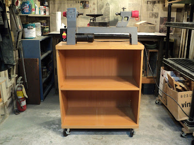
Here it is doing what I wanted it to, holding up a small wood lathe. Not a bad outcome for what I paid for it.


* * *

Note:

[1] Busy Bee Cat. No. B17863 -- set of four casters w/brakes.


# # #


# # #