Thursday, September 25, 2014

Roadside Find -- A Marble Disc


My wife today found this exquisite marble disc by the side of the road.


It's 15" in diameter and 5/8" thick. It weighs almost 11 lbs.

The only bad news is that the underside features a disgusting puddle of hardened adhesive of some sort, like so.


Hmmm. I'll have to see what, if anything, will remove that mess.

- - -

Paring with a sharp utility knife blade got most of it. Lacquer thinner seems to dissolve what's left, albeit slowly. Here's my progress so far.


At least it's fit to be the disc's underside now.

- - -

I have no idea what I'm going to do with this item, but it begs me to find something very good to do with it.

To be continued, God only knows when.

# # #


# # #

Thursday, September 18, 2014

A Flowerpot Coaster


My wife has an indoor flowerpot that needs a non-scratch treatment for its bottom. The pot is very nice, but it's not something that can be safely placed on top of a finished surface -- it's liable to scratch what's underneath it. Here's a view of the flowerpot.


Underneath, there's a narrow 'rim' that's the problem.


A wooden disc 'coaster' would be a good solution, and it might make for an interesting bit of faceplate work on the wood lathe.

I have a rectangle of 9/16" thick particleboard that's big enough.


Particleboard is probably the worst possible material I could select for this, but that's reason enough to go ahead and try it anyway. Everything in life is ultimately just an experiment, so I'll experiment with particleboard here as a flowerpot coaster material.

First up is to cut that rectangle into a rough disc with a jigsaw, then mount it on a faceplate.

- - -

And here's that much done.


Now I can see what it's like to turn a true, rounded-over edge on that piece of trash material.

- - -

It can be done.


It takes a sharp gouge, presented to the work at a steep angle. You don't get shavings -- you get dust. The porosity at the centre of the material's thickness is awful.

And as long as I'm experimenting here, I may as well experiment with filler for the porosity. Here's the disc after a liberal application of Bondo glazing & spot putty.


I've been meaning to try out Bondo as a woodworking filler in places where it will get painted over, and this will be an ideal trial.

- - -

After hardening and sanding, the Bondo appears to have served remarkably well.


The Bondo did quite a nice job of filling the particleboard's edge porosity.

I'll see this through to completion with primer and paint, and I should have a perfectly good flowerpot coaster to show for it.

- - -

Update -- THURSDAY, SEPTEMBER 18, 2014

After primer and two coats of flat black enamel, here's what I've got.


It's not quite flawless, but it's close. I missed some tiny spots with the Bondo that don't show in the photograph. All in all, I'm quite pleased with the results I got from the Bondo -- it gave me a presentable, useable coaster from a piece of utter trash material.

The coaster fits the underside of the flowerpot nicely.


And it does exactly what it's supposed to do.


It keeps the hard, ceramic base rim of the flowerpot up off a surface, almost invisibly.

# # #

FEEDBACK

# # #

Sunday, September 14, 2014

Gas Water Heater TCO (Thermal Cut-Off) Trouble


Pictured above is a typical gas water heater's TCO (Thermal Cut-Off), where it resides on the heater's combustion chamber wall. (The TCO's two wire connections have been removed in the photo.) The TCO is there as a safety feature -- in the event of an over-heat condition in the water heater's combustion chamber, the TCO will go open, disabling the burner and the pilot light.

A defective TCO that goes open for no good reason will cause a very deceptive trouble symptom to arise; i.e. the pilot light will be disabled. You'll still be able to relight the pilot light, but the pilot light won't stay lit -- exactly the same symptom you'd expect from a bad thermocouple.

A continuity test with an ohmmeter will not necessarily reveal the fault in the TCO. The TCO may check out ok with an ohmmeter applied to it, but fail intermittently while in service nonetheless. To be absolutely, positively certain whether or not you have a TCO fault, bypass the TCO altogether with a splice connector, like so.


If the water heater works reliably with the TCO bypassed, you'll know that the TCO is at fault, not the thermocouple.

The TCO in the above photographs gave me exactly the trouble I've just outlined. One of its spade terminals is a little bit wiggly; that may be the cause of its intermittent, deceptive behaviour. Here's a close-up view of the thing.


The spade terminal at the unit's upper right is the wiggly one. I may be able to repair that with a hammer and punch. If not, I'll have to obtain a replacement.

In any event, I've saved myself a costly service call, and the water heater is back in business for the time being with its TCO bypassed. I'll take my chances with the safety feature's absence.

# # #


# # #

Friday, September 12, 2014

A VOM (Volt-Ohm-Milliammeter) Repair


I occasionally leave my brain in 'Park', while the rest of me engages 'Drive'; stripped gears are liable to ensue.

For example, I was using this old VOM (Volt-Ohm-Milliammeter) for something-or-other, and I neglected to mind the range switch as I went from measuring a resistance, to checking AC line voltage.


Applying AC line voltage to a VOM that's set for resistance measurement has an unfortunate effect on the instrument -- it renders the affected resistance range inoperative and, in this case, it took out the custom-made battery-eliminator/power-supply that I had designed for the thing long ago.

Fortunately, repair was not difficult once I'd obtained an ancient IC (Integrated Circuit) off of Ebay. The IC is a 723 voltage regulator dating back to the early 1970s, when I was an electronics engineering technology student at DeVry. Here's a view of the power supply's innards.


And here's a close-up of the affected IC.


I'm glad I chose to mount that IC in a socket.

With a new IC in place, the power supply was good to go. That left me with the damage to the VOM itself to deal with.

When you apply AC line voltage to a resistance-measuring range of a VOM, you destroy a resistor pertaining to the range that was selected at the time, like so.


The resistor smokes and goes open, rendering the related resistance range of the instrument inoperative.

A replacement resistor ought to be a precision type of the exact same value, but obtaining one of those would be a bit of a costly ordeal. A quick-and-dirty solution is to just use common, spare 5% tolerance resistors in whatever combination is needed. Here, I've installed a 150 ohm resistor in series with a 10 ohm resistor to give me a 160 ohm 'ballpark' replacement.


That worked fine, and got me back my VOM with all of its functionality more-or-less intact.

Now, if I'll only learn to pause and check the instrument's range switch when I ought to, there won't be a recurrence of that sort of incident.

# # #


# # #

Friday, September 5, 2014

Noma Gran Prix Snow Blower -- Impeller Bearing Failure


* * *

NOTE; I was remiss here in not photographing and documenting this matter as I took the machine apart. I'll try to do a decent job of recording the reassembly. I hope the reader may still find it of some interest or use.

* * *

The old snow blower my son bought turned out to have a severely worn impeller[1] bearing.[2] Here's a view of the thing removed from the rear of the snow blower's scoop where it resides.


It's well and truly 'game over' for that bearing.

The previous owner of the snow blower had continued to use the machine with the ruined bearing in place. That had the effect of hammering down the diameter of the impeller's shaft under the inner race of the bearing. The shaft there was about 0.013" undersize from its original 7/8" diameter.

The only way to get the shaft fit for service again was to have a machinist knurl the undersize portion, to raise crests that would again fit the inner race of a bearing. Here's a view of the knurling job done.


The crests of the knurls now represent a slight oversize of 7/8" diameter. To be able to reassemble the mechanism, I'll have to file the crests down just enough to give me a sliding fit in a new bearing. I'll do that by hand on my wood lathe, using the old bearing as a reference. Here's a view of that setup.


Done. The new bearing is now a sliding fit on the knurl.


At final assembly, I'll apply some Loctite retaining compound to the knurl, so there'll be no looseness to the bearing's fit on the shaft.[3] That may be a bit of an iffy proposition, because I'll be asking quite a lot of the retaining compound -- the retaining compound may not cure in voids as large as the knurls' valleys. Should that transpire, I'll redo the assembly with CA adhesive instead of retaining compound.

Anyway, it's time to get the impeller reassembled with its gearcase and the augers.

- - -

And here's the whole auger/gearcase/impeller affair back together and ready for installation.


Tomorrow, weather permitting, I'll get all that back into the scoop along with its new bearing.

- - -

The Weather Cooperated -- SATURDAY, SEPTEMBER 6, 2014

And here's the new bearing bolted in place at the rear of the scoop.


Here's the auger/gearcase/impeller assembly stuffed back into the front of the scoop.


And here's the impeller's shaft-end in place at the rear of the scoop, awaiting its pulley.


The machine is ready for final reassembly.

- - -

All Done -- MONDAY, SEPTEMBER 8, 2014

Here's the machine back together.


And here's a closer view of the v-belt transmission.


The locomotion belt at the right has no tension adjustment. Its tension is set by its spring-loaded idler pulley.

The auger drive belt at the left is adjustable for tension -- its idler can be repositioned in a slot for optimal tension when auger drive is engaged.

From what I've seen on this machine, snow blower auger/impeller drive is a brutal, stressful job. It's an area in any used machine that's likely to need attention. All in all, I think my approach to repairing this one was sound. The proof will be in how it stands up to the coming winter's work.

- - -

Notes:

[1] "Impeller" is my term for the second stage element of a two-stage snow blower. The 'auger' is the first stage. The auger sweeps up snow and hands it off to the second stage, the 'impeller'. The rotating impeller hurls the snow up and out the chute.

[2] The bearing's description as it appears on the sales receipt from my parts dealer is, "44-053: 9648/780048 Canadiana Keyed Bearing". It's a 1640ZZ bearing with a 3/16" keyway in it's inner race. Dimensions are 7/8" bore x 2" O.D. x 9/16" thick.

[3] As it turned out, I decided against using any retaining compound or adhesive at the bearing's inner race, where it fits over the shaft.

The bearing is an easy sliding fit on its shaft, even where the shaft still has its undamaged, un-knurled surface. The fit has to be relatively loose for the sake of ease of assembly. Were it a snug fit, it would be extremely difficult to install the auger/gearcase/impeller assembly in the scoop. That's no doubt why the bearing's inner race is keyed -- so that the loose fit won't result in the shaft turning within the bearing; the keying forces the bearing to be operative, in spite of the loose fit of the shaft.

# # #


# # #

Wednesday, September 3, 2014

A Spindle-Turning Lathe Restoration -- Part II


* * *

Part I of this post is here.

* * *

Leg Weldment Preparation -- WEDNESDAY, SEPTEMBER 3, 2014

There's not much to tell about this aspect of the restoration; it's mostly just a matter of getting the weldments clean enough to accept a rudimentary paint job, as I did a bit earlier with the unattached angle braces.

The legs have cross-rails that would be ideal for supporting a plank shelf underneath the deck. To make use of that feature, I have to grind a couple of lumpy welds, and drill two 1/4" holes in each cross-rail, like so.


My 4 1/2" angle grinder took care of the lumpy weld; that turned out fairly well. That steel angle was not difficult to drill with a portable drill. I'll give the other weldment the same treatment, and I'll have decent shelf supports ready for when the legs and deck are back together again.

Here's a view of the weld that's still to be ground.


Once the grinding and drilling are out of the way, I'll clean and sandblast the two weldments and get them set up for painting. With that done and the deck painted, the lathe will have a presentable stand.

Preparing The Deck For Painting

The deck is a frightful mess -- riddled with holes and badly scarred. It's going to take a lot of filler and sanding to get it fit for a paint job.

One thing I should point out concerns the use of filler -- the more you can minimize the use of filler, the better. Small holes and flaws can be filled with filler only, but outright large holes should be filled with glued in bits of dowel, as I did here.


Make the dowels' lengths such that the dowels' ends sit just below flush with the surrounding surface. Then, an application of filler, once sanded, will present a uniform surface for paint.

Anyway, that's about it for now. Once I've gotten done with the heap of tedious work that I have ahead of me here, I'll return with a view of the completed lathe stand.

- - -

Back Early -- SUNDAY, SEPTEMBER 7, 2014

The first leg weldment is looking good. Here's a view of it after two coats of Tremclad grey.


What a difference a paint job makes.

- - -

Stand's Done -- THURSDAY, OCTOBER 23, 2014

Here's the stand fully painted and assembled.


It's very rigid; it should be well up to its job. A shelf spanning the two lower leg weldment rails wouldn't hurt.

What I'll do from here on is get the un-refinished lathe fully assembled and operational, and add the shelf I just mentioned. Once the machine is completely satisfactory, I'll tear it down again for a paint job.

- - -

Getting It Together -- TUESDAY, OCTOBER 28, 2014

Here it is on its way to operability.


The motor mount is installed, and the motor wiring is done. I want to replace the v-belt with a link-belt style of belt. The stiff, old v-belt that I have for it now is noisy, and I 've been looking for an excuse to get some experience with link-belt installation.

The tailstock casting is painted 'shutter green'. That's to be the colour overall, with a few grey accents. (Grey goes with anything and everything.) I'll leave the upper surface of the bed ways unpainted, so as not to interfere with smooth sliding of the tailstock.

- - -

TheTailstock -- WEDNESDAY, OCTOBER 29, 2014

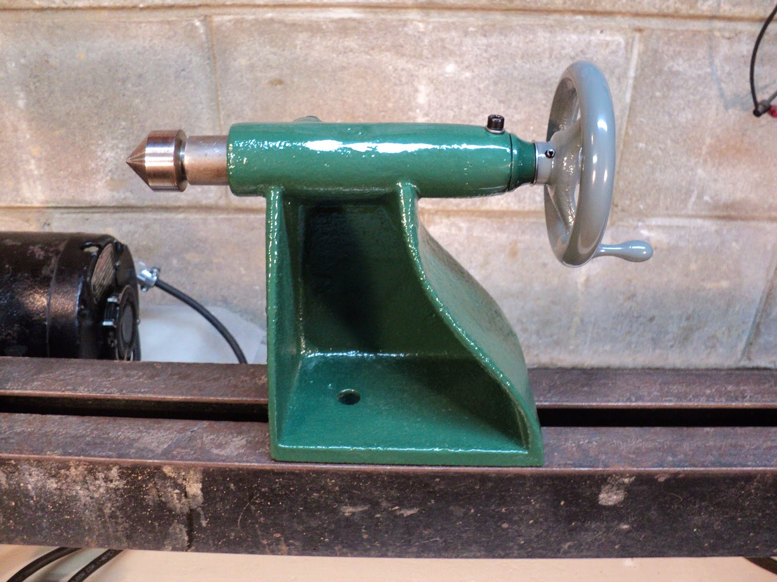
Here's the tailstock fully painted and reassembled.


I'm very pleased with the colours.

The centre's meet-up with a centre in the headstock was a bit low, so I shimmed up the front of the headstock casting with a couple of washers, like so.


I glued the washers in place with CA adhesive. They appear to be quite secure. We'll see how that shimming job holds up to service.

The taper of the dead centre and the tailstock ram is nonstandard. It's a deviant form of MT2 taper that I've never encountered before. It's an impediment to having a fully functional tailstock, that will accept different centres and accessories. I'll have more to say/show about that later on.

- - -

The V-Belt

The original v-belt was delaminating and done for, plus it was way too long for my revised motor mount arrangement. I had a stiff, old v-belt that fit and worked, but it had a 'set' to it that made it lumpy and noisy.

Busy Bee carries a link-style v-belt that I've long wanted to try out. It's made by Fenner Drives; it's Fenner Drives PowerTwist Plus A/13. It's sold by the foot. Here's a view of the three-foot length that I bought, along with a couple of loose links.


The A/13 size shown replaces 4L (1/2") v-belts.

The stuff is fairly easy to work with, once you get the knack of disconnecting and re-hooking the links. It didn't take me long to get my approximate length of belt material to where it fit the motor mount's tension adjustment range nicely. Here's a view of the installed belt.


Note that there's a directionality to the belt. Every tenth link has an arrow printed on it, so you can't go wrong.

The belt runs pretty smoothly. It's not cheap; Busy Bee's price is $9.99 per foot. Nonetheless, I'm sold on the stuff.

- - -

Painting The Foot Castings -- THURSDAY, NOVEMBER 6, 2014

It seems like every time I spray paint something, I find myself thinking, "There. That's got to be the most awkward thing to spray paint that I'll ever encounter." And then, the next thing comes along and proves to be even more awkward. Such was the case with the first of the two foot castings. Here's a view of how I rigged it for painting.


That vise is on a turntable -- it simplifies things a bit when spray painting many items.

All things considered, it's not a bad outcome.


It certainly looks better than the casting that's still to be painted.


- - -

Operational -- SATURDAY, DECEMBER 6, 2014

Here it is with the basic components painted. It's ready to turn something.


And here's the lathe's first project -- a handle blank for a knockout bar.


Done.


Now I have  proper knockout bar for dislodging centres from the spindle's taper.


I'm getting the feeling that I could make a career out of this lathe.

Next up is to make what improvements I can to the tool rests and paint them.

- - -

One Toolrest Done -- MONDAY, DECEMBER 15, 2014

Here's one of the lathe's toolrests repaired, painted and fit for service.


I think the original toolrest(s) went missing, and was/were replaced by locally fabricated equivalents. The fabrications are pretty rough, but serviceable.

The Steady Rest


It's quite the construction. It needs some work. The screws/nuts are all seized, and one of the three bearings is seized. It's all not in too bad a condition, though, so it should be recoverable with a little TLC.

- - -

And here's the steady rest all recovered and ready for use.


And with that, I'll close off this post and get on with putting the lathe to use.

# # #


# # #