Friday, October 26, 2012

Backyard Archaeology II


The first 'Backyard Archaeology' post I did was about an old 6" diameter wheel that turned up when some retaining wall work was being done at the back of the house.

Here's another item that got dug up along with the wheel:


The scantest remains of a garden fork. Turning that back into a useful tool will be a righteous challenge. I have the makings of a handle-shaft on hand. Some wire-brushing is in order for starters. We'll see how this goes.

# # #


# # #

Saturday, October 20, 2012

An Unorthodox Coupling Nut Application


I've written before about coupling nuts -- about what a useful, versatile standard hardware item they are. Here's another example of an unorthodox application that got me what I needed with a minimum of machining.

- - -

The Problem

I have an old 230V space heater in my workshop that works fine, and looks likely to last forever. It has one little annoying feature, though -- its thermostat is mounted at the lower rear of the unit, like so.


(That's actually a sensible place for the thermostat to be, where it can determine when to switch off based on the temperature of the incoming air.)

The way I have the heater situated, it's awkward to have to reach around to the lower rear of it to switch it on. I could see a way to install a control knob in front while leaving the thermostat in place at the rear, but I needed to fabricate a 3/16" diameter rod-coupling with a little bit of axial 'give' to it to compensate for imperfect alignment of components. A 1/4"-20 coupling nut came to the rescue. Here's a view of the rod-coupling I came up with.


I love that sort of work. I won't bore you with all the details of it as I'm usually prone to. The key to success is extremely careful layout, centre-punching and setup in a good drill press vise.  The key to the coupling's axial 'give' is the cotter-pinned end. That part of the coupling is 'sloppy' enough to compensate for an imperfect rod axis from front-to-back of the heater. The setscrew fastening at the coupling's other (left) side end gives angular adjustability, so the knob can be positioned correctly angularly.

The brass bushing at the left was glued onto its shaft-end with CA adhesive. The brass bushing at the right was left a free slip fit. Here's a view of the coupling installed in the heater.


And here's the front of the heater with its new control knob.


The knob's 'directionality' is the reverse of what it should be, but that's not difficult to get accustomed to. The whole arrangement works perfectly. (Concealed by the knob is a Heyco SB 312-3 snap bushing that's serving as a 'bearing' for the control shaft.)

Anyway, that's a good example of the versatility of coupling nuts. I could have fabricated much the same thing from scratch from a similar length of plain steel rod, but the hexagonal coupling nut was easier to work with for my purpose here.

# # #


# # #

Sunday, October 14, 2012

Work Habits -- Picking Up and Putting Away


[That's not a picture of my place. I just threw that picture in for effect.]

- - -

It never ceases to amaze me -- the number and variety of tools, parts bins, adhesives, solvents, lubricants, what-have-you that get brought to bear on the seemingly simplest, tiniest of projects. Every time I tackle anything, by the time I'm done with it, I seem to have put to use eighty percent of my workshop's resources in one way or another.

There's no escaping that, and it can result in mind-boggling workbench clutter if you let it. Now, I know there are those who can cope with frightful clutter, and keep on working in the midst of it efficiently and effectively,  but I'm not one of them; workbench clutter eventually causes my brain to seize up. I reach a point where all I'm aware of is the clutter, and I can no longer function. I have to take a time-out to pick up and put away everything before I can carry on with the project at hand.

I long ago decided that the best way for me deal with clutter was to nip it in the bud, minute-by-minute if need be. What I do is I constantly review what it is that I actually need to have right at hand on the workbench. If I tap a 6-32 thread, as soon as it's done I ask myself, "Any more of those to be done on this?" If the answer is 'no', the tap and the tap wrench go directly back to where they belong; I don't leave them to loiter on the bench. I apply that little test to everything as I go along.

I find that there's really no down side to that practice. Once I'm done with a session of whatever, the 'picking up and putting away' left to be done is near zero; things don't get misplaced -- they're always back where they ought to be, and the bench is cleared and ready for the next session, whatever that may consist of.

Anyway, as I said earlier, I know there are those for whom what I've just been on about is not a concern at all -- they can happily work away amidst clutter that would have me running for the exit. But if you're one for whom clutter is an irritant, there's an easy way to keep it at bay -- just make it a habit to nip it in the bud as you proceed with whatever you're doing.

# # #


# # #

Monday, October 8, 2012

Belt Sander/Grinders


My dad found this old Delta sanding machine some years ago.


It was in pretty rough shape. The disc sander's table was missing, the 8" diameter disc had a lot of axial run-out and the belt sander's plastic pulleys were badly out-of-round. I gave up on the disc, I have an adequate disc sander anyway, but I trued up the belt pulleys on the lathe and replaced their bearings. That got the belt sander portion working reasonably well, and gave me an introduction to what a 1" x 42" belt sander/grinder can do. I was impressed. A lot of tool sharpening chores are made much easier. Grinding with the belt is a cooler-running operation than with a grinding wheel, and the table opens up possibilities for creating fixtures to 'de-skill' certain jobs.

However, the three-pulley architecture of the Delta machine leaves a bit to be desired. I've never been entirely happy with the way the belt tracks, and I don't expect the plastic rims of the pulleys to remain true indefinitely. (I'm already getting a bit of 'shimmy' from the belt.) So, when I saw a two-pulley sander/grinder[1] on offer at Lee Valley for a reasonable price I thought, "Hmmm. That may be the way to go." A bonus was that the Lee Valley machine takes the same size sanding belt as the Delta, so all my spare belts would remain useable

A couple of weeks ago I went to a Lee Valley store, parted with the requisite number of dollars and brought home a box full of assemble-it-yourself sander/grinder. We'll see how this goes.

- - -

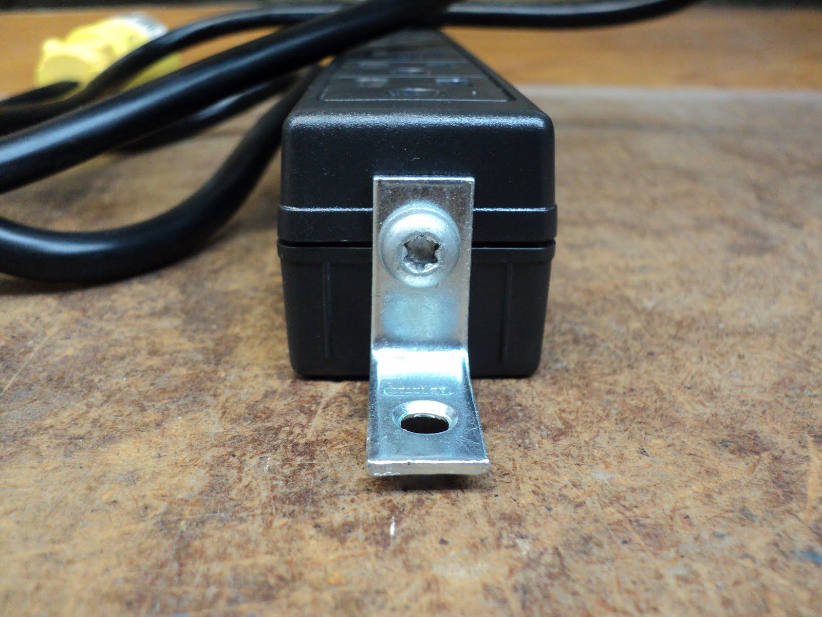
The Lee Valley machine is a supply-your-own-motor deal. The motor's shaft diameter must be 1/2", rotation must be CCW as seen shaft-end-on. I have a spare 1/3 hp motor[2] that will do nicely. I'll rob the Delta machine of its switch and wiring, and I'll have the motor taken care of.

The machine's base comes with rubber 'feet' attached. The feet are adequate, but they look kind of dinky to me. I have some taller, more substantial feet that I'll install in their place.


- - -

With that done, assembly of the machine is straightforward. (An adequate if unimpressive 'manual' comes with it.) I gave it a trial run, and the belt's tracking is good but not perfect. Here's a view of the drive pulley.


The belt wants to track slightly off to the left. To correct that, I'll need to shim up the front end of the motor very slightly -- easier said than done. I have an idea for a way to build a tracking adjustment into this machine, and I think I'll pursue that and see how it works out. I'll be back with that when I get it done. Meanwhile, it looks like I've got a good replacement here for the old Delta boat anchor.[3]

- - -


Update -- SATURDAY, OCTOBER 27, 2012

I've prepared the chassis for the tracking adjustability modification I have in mind. Here's a view of that.


That beige steel rectangle will shim up the front end of the motor. The furniture glides will elevate the chassis so there'll be about an inch of clearance underneath it. (I glued inner-tube rubber discs onto the glides with CA adhesive, so the machine won't 'walk'.)

Two modified 5/16"-18 tee-nuts will be force fitted into those two chamfered 25/64" diameter holes I drilled. (Unmodified tee-nuts are shown down in front.) I could have drilled tap-size holes and threaded the base plate directly, but installing tee-nuts gives me far superior threads.

The idea is to shim up the front of the motor more than is needed, giving the machine an inherent, initial tendency to track the belt too far rightward, Then, by means of short 'jack' screws installed from below, I should be able to slightly elevate the rear of the motor as needed to adjust belt tracking. I would like to have only needed one central tee-nut, but the base of the motor-mount is mostly hollow along its centre, so I had to go with two tee-nuts. Here's a view of the chassis with the tee-nuts and feet installed.


And fully reassembled, It works as I thought it would.


The machine now has on-the-fly adjustable belt tracking. (It's easy to tip the machine rearward for access to the adjustment screws.)

Key to the adjustability is the installation of the rear motor-mount bolts. The front bolts and nuts are fully tightened, of course, but the rear bolts aren't. The rear bolts are partially tightened against split lock washers, like so.


That provides a sprung downward bias for the rear of the motor mount that the two adjustment screws underneath can operate against to effect the tracking adjustment.

Anyway, I'm quite pleased with that outcome -- it's a worthwhile modification. There's still more to show and tell about this machine, but I'll leave it at that for now.

- - -


The On/Off Switch Fitted -- SUNDAY, NOVEMBER 11, 2012

Here's a view of the simple way I adapted the old Delta switchbox to the chassis.


I just fabricated an 'L' bracket from some 1 1/2" wide steel flat stock, and attached it to the chassis at the left rear foot's stud. That's certainly an improvement from having the switchbox just out flopping about on the line cord. Now the machine is a proper, self-contained unit.

- - -

Platen Tracking -- SATURDAY, NOVEMBER 17, 2012

The 'platen' is a flat steel bar that backs up the working portion of the abrasive belt between the two pulleys. The belt tracks a little off to the right with respect to the platen; it ought to track centred on the platen. Here's a view of the flaw.


I could shift the drive pulley leftward on the motor's shaft a bit to correct that, but I'd also have to fiddle with upper pulley's positioning. I'd rather take the easy way and just shim the platen rightward a little by installing two washers where the platen attaches to the chassis.

1/4" flat washers are thicker than what's needed. I have some 3/16" fender washers that are about the right thickness. I'll bore two of those out to 1/4" I.D. and they should do fine.

- - -

And here's a view of the platen re-installed with the two shim washers in place.


That takes care of that.

Tomorrow, I'll have something to show about the upper pulley, and then I can get on with putting this machine to use.

- - -

The Wheel Mount -- SUNDAY, NOVEMBER 18, 2012

Viel's name for the item that supports the upper pulley is 'wheel mount'. Here's a view of it with a slight modification that I made to it.


I wedged a piece of 3/4" thick softwood in between the uprights to make the thing more rigid. Prior to doing that, tightening up the screws on either side at all tended to distort the wheel mount's uprights.

The loose fit of the wheel mount in its tube, along with the screws at either side, provide a bit of pulley alignment adjustment. My machine appears to be happiest with the wheel mount biased fully rightward. Note that pulley alignment is not the same thing as belt tracking. Belt tracking is adjusted by shimming the motor, and must be resolved first, as was done here.

- - -

The Table

The machine's table is well-thought-out and nicely made; it has a huge 'tilt' range, like so.


That's far superior to the table geometry I had on the old Delta machine. I think I'll spend some time sharpening cold chisels.

- - -

That was the easiest sharpening work I've ever done.


(That blade at the right is the plane iron from from a small block plane.)

That was a breeze. It's amazing how coolly the belt grinds; you'd have to be trying to 'burn' a cutting edge with the thing.

Anyway, no regrets about retiring the Delta beast and acquiring this machine. It was money well spent.

- - -

Update -- SUNDAY, MARCH 10, 2013

I've had the use of this machine for a few months now, and I'm delighted with it. It's proving to be one of the most useful pieces of gear in my workshop.

- - -

Addendum -- A Table Tilt-Lock Improvement -- MONDAY, JUNE 10, 2013

I found it a nuisance to have to use two wrenches while making adjustments to the table's angle, so I pinned[4] the head end of the 1/4"-20 screw, like so.


I also substituted a light split lockwasher for the standard one, and added a flat washer under the nut, over the split lockwasher.

I find the easiest way to make the tilt adjustment is to have the nut loosened just enough that the table is free to pivot, but will stay at whatever angle it's set to. Then, slide the table off for good access to the nut, and tighten the nut. The angle you've set won't be altered at all as you tighten the nut.[5] Re-install the table, set its distance from the belt, and you're away.

- - -
Notes:

[1] The machine is made in Rivière-du-Loup, Quebec by Viel Tools. Viel's on-line price is a little less than Lee Valley's, but Lee Valley has a store that's handy to me, so I wouldn't save anything by having one shipped to me from from Quebec.

[2] Lee Valley calls for a minimum 1/8 hp motor. 1/4 hp would be ideal. 1/3 hp is more than what's needed, but it's what I have on hand and idle, so I'll put it to work here. The Delta motor's shaft diameter is 5/8", so it's unsuitable for the new sander/grinder.

[3] I'm always inclined to think, with respect to workshop machinery, that 'the more massive, the better'. That line of thought is not fallacious, but it's not infallible; the belt sander/grinders seen here are illustrative.

The old Delta machine is a massive, heavy piece of gear. The Viel machine is a fraction of the Delta machine's mass/weight, yet the Viel machine does the job at least as well if not better. There's a lot to be said for 'minimalism' sometimes.

[4] A 3/32" x 5/8" roll pin would work. I used a 5/8" long steel dowel pin that I happen to have a supply of. The pin is 0.092" diameter -- just shy of 3/32". I drilled through 5/64", followed by No. 43 (0.0890"), followed by No. 42 (0.0935"). That gave me a light interference fit for the pin.

The reason that worked out as it did is because of a peculiarity of twist drills. Twist drills are not reamers. When an existing hole is enlarged by the next size up of drill, the resulting hole is likely to be a bit undersize. That characteristic can occasionally be exploited to good effect, as I was able to do here.

Since I drilled all the way through, I'll be able to punch out the pin should I ever have reason to dismantle the thing again.

[5] Warning -- WEDNESDAY, OCTOBER 16, 2013

What I just said there is not necessarily true, I've since discovered. It's helpful to oil the washer arrangement, but that's no guarantee that table angle won't shift on you as you tighten the nut. A better way to deal with table angle adjustment may be to tighten the nut to where the table remains hand-adjustable with some difficulty. At that tightness, the table's angle is unlikely to be altered by normal use forces.

# # #


# # #

Sunday, September 30, 2012

A Discarded HP (Hewlett-Packard) mPDU

My boss at work found this and thought I might have use for it.


It's an HP Modular Power Distribution Unit (mPDU). Not shown in the photo are three more power bars, and a heap of steel brackets and fasteners. It's all brand new; it was in its original box.

It seems a school was throwing it out,[1] so my boss snagged it. I don't have use for the breaker/distribution box, but the power bars I can certainly make use of -- I just have to replace the peculiar plugs they have with standard ones.

The power bars' line cords exhibit something I've not seen before -- the wire gauge expressed in both American Wire Gauge (AWG) and metric. The AWG number is '14'; the metric 'gauge' is 1.5mm2. Looking up a combined AWG/metric wire gauge table reveals that 1.5mm2 is actually a bit shy of 14 AWG, so the cords are either 'light' 14 AWG, or 'heavy' 1.5mm2. It strikes me that the metric 'equivalence' figure here is at best unhelpful, at worst misleading.

Anyway, enough of that.

I picked up four Leviton No. 515PV plugs to make the power bars useable. They're the type with clamp-style terminals that I find to be easy to work with and very reliable. Here's a view of one opened up.


Installing these is a no-brainer, really, but it's nice to have predetermined dimensions for jacket and insulation strip length. I'll go with 1" for the jacket, 3/8" for the hot and neutral wires and 1/2" for the ground wire. Here's how that looks.


The colour coding is international, not North American. Here's the equivalence in the form 'Function/N.A. colour/Int'l colour'.

Line/Black/Brown

Neutral/White/Blue

Ground/Green/Green with Yellow Tracer

It's easy to remember the international colours if you think of 'line' as 'hot', brown as a 'warm' colour and blue as a 'cool' colour.

I like to tin stranded conductors with 60/40 electronic solder and flux. Here's how that looks after the flux residue has been cleaned off.


Those strip length dimensions I used make for a nice, compact installation that for certain will fit the shell and the strain-relief clamp correctly, like so.


Now I've got the use of one of the four power bars; I just have to come up with a way to mount it. The mounting provision is an M5 threaded hole at each end of the bar, like so.


The brackets that came with the mPDU are all odd looking things meant for mounting the bars in an electronic equipment rack -- they're not suitable for mounting to a flat surface as I have in mind. A common one-inch corner brace may be a simple solution.


That will work, but I'll need some 1/8" thick material for shim 'washers' to take up the space under the corner braces.

A while ago, I came up with a neat method for ripping odd thicknesses of shim/spacer material on the table saw. I'll apply it here and I'll have just what I need shortly.

- - -

And here we are.


Now I can replace this clunky old arrangement.


And here we are.


Much better. That corner brace and 1/8" shim mounting arrangement turned out well; that power bar is solidly attached to the bench leg.

By the way, having plenty of well-situated, permanently installed power bars in a workshop is a great convenience -- well worth the expense to acquire them and the work to install them. I dislike extension cords; they're a nuisance and a trip hazard. I have something like six power bars installed here and there in my shop, and they save me a lot of aggravation.

- - -

Note:

[1] I could go off on a rant here about government waste, but that would be futile. Waste is everywhere in our economy; the economy practically runs on the production of waste. At least in this case, I was able to intercept a bit of it to my advantage. Good. And if some school wants to throw out a new milling machine and some welding gear where I can find them, that would suit me just fine.

# # #


# # #

Monday, September 3, 2012

Slacking Off


Just in case anyone's been wondering why the workshop's been so idle lately, here's the reason.

# # #


# # #

Saturday, August 25, 2012

Lexicon -- Backlash/Lash


Strictly speaking, the accepted term for clearance between mechanical components, especially with respect to the mating teeth of a geartrain, is 'backlash'. At Dictionary.com, I found this etymology:

'backlash  1815, of machinery, from back (adj.) + lash. In metaphoric sense, it is attested from 1921.'

It seems to me that the 'back' portion of 'backlash' introduces a needless specificity to the term for many purposes. Hence, I'm inclined to simply use the word 'lash' as a catch-all term for any sort of clearance/play/slop in a mechanical relationship, even though I can find no authoritative support for that usage. Though I tend to be a stickler about correct, authoritative word usage, in this particular case I'm entirely at ease with taking the attitude, "Authority? We don't need no stinking authority!"

# # #


# # #

Sunday, August 19, 2012

Immobilizing a Lathe Spindle

My lathe has no provision for locking the spindle, and I needed to lock it so I could tap a thread in something chucked in the scroll chuck. I came up with this arrangement.


There was already an unused hole in the side of the switchbox that was the perfect size for tapping a 10-32 thread. A length of 8mm diameter rod and a 5/16" cable clamp now provide an adequate spindle lock for what I need to do.

- - -

An Improvement -- SATURDAY, AUGUST 25, 2012

I've added a second cable clamp near the spindle to minimize lash. Here's a view of that with the chuck dismounted.


Much better.

- - -

Addendum -- SATURDAY, NOVEMBER 24, 2012

I just discovered a little glitch. When I went to mount the lathe's four-jaw chuck, the parked spindle lock rod interfered with the jaw nuts on the back of the chuck. I had to remove the cable clamp nearest the spindle, and back the rod well away.

# # #


# # #

Saturday, July 21, 2012

Whirlpool Dishwasher Won't Drain

Odds are that the reason a dishwasher won't drain is that its drain check valve[1] is clogged with debris. The check valve is fairly easy to get at and deal with. You'll need a No. 2 Phillips screwdriver, a set of Channellocks, and something to use for a drain pan.

Remove four screws to get the two access covers off the lower front. Set your drain pan in place, and back off the big spring-type hose clamp from the rubber elbow you'll see at the end of the check valve. Slip the rubber elbow off the end of the check valve and you'll likely have this.

A slow dribble of murky water. If the water gushes out of there freely, the check valve is not the problem, and a 'Plan B' is in order.

Patience is needed here. It took four half-fillings of that big frying pan to completely drain the dishwasher.

With the draining over with and everything cleared away, it's fairly easy to unscrew the check valve to examine it. Here's a view of the check valve out of the appliance.


That thing's inside diameter is only 10mm, so it doesn't take much to clog it. Here's what I yanked out of it with a spring hook.


I have no idea what that grotesque little object is -- it's quite hard, and it's certainly not something that we eat around here. Whatever it is, it had no business getting into the dishwasher. This is why the very first thing the user's manual tells you is, "Scrape large food soil and hard items (toothpicks or bones) from dishes."

Anyway, with the check valve and its gasket-seating surfaces cleaned, everything went back together easily. Before replacing the access panels, I ran a 'fill' and 'drain' cycle to check for leakage. All was well, so the dishwasher is good to go again.

- - -

Note:

[1] As I understand it, the drain check valve is there so that in the event of some freakish mishap with a sewage system (as might occur in a flood, say) sewage water can't back up into the appliance. That's an excellent reason for the check valve to exist, but it does make for a somewhat constricted drainage opening.

The actual 'valve' inside the part pictured above is just a resilient flapper-valve located at the point where the diameter increases. I tried blowing through the valve in the 'check' direction, and it leaked, so how much good the valve would do if it were ever actually needed is questionable.

# # #


# # #

Sunday, July 15, 2012

A Wire Wheel Machine


I often refer to 'wire-brushing' when I write about restoring old gear. By 'wire-brushing', I seldom mean the use of these.


What I'm usually referring to is the use of this machine.


I'd be lost without the thing. It gets a lot of use here.

I built it many years ago from a 1/3 hp motor, and a ball bearing mandrel that I think I found at Canadian Tire. No one seems to make these ready-to-go; you pretty much have to construct your own to have one.

The drive ratio is approximately 2:1, so the no-load wheel speed is about 3,600 rpm.

The wheel is a fairly stiff 6" diameter one. 6" is an adequate wheel diameter, and that wheel has served me well. 8" would be better, though, and I mean to get an 8" wheel for it eventually. (When I was constructing the machine's base, I made sure to provide clearance for an 8" wheel.)

The safety police would likely taser me for that exposed v-belt drive, but there are no kids around here to worry about, and I can't be bothered making a belt enclosure for it. Different circumstances might dictate that a belt enclosure should be provided.

The one safety feature I did install was a guard for the on/off toggle switch, like so.


I fabricated that from sheet aluminum. It precludes inadvertently hitting the switch at an inopportune time.

Further to safety, don't even think about turning on a wire wheel machine without wearing eye protection. No necktie, dangling draw-cords or loose shirt sleeve cuffs, either.

Anyway, it's an indispensable item for repair and restoration work, and not difficult to construct. Google "ball bearing bench mandrel" and you'll find mandrel suppliers.

* * *

Update -- FRIDAY, APRIL 18, 2014

I finally got an 8" wheel for the machine. Here it is installed.


The wheel is from Busy Bee; Cat. No. B355.

The wheel's bore is 32mm. It comes with a set of molded plastic bushings for adaptation to fractional inch shaft diameters, like so.


Sizes are 1/2", 5/8", 3/4", 7/8" and 1".

The wheel runs reasonably true and balanced, in spite of the hub's somewhat wobbly appearance on the mandrel. The wheel's balance is not perfect -- it generates some vibration, but it's tolerable. The wheel is rated for 4,500 rpm, so my 3,600 rpm machine is well within that. (3,600 rpm seems to be a good speed; I wouldn't run one of these wheels any faster.)

The wire ends' finish at the wheel's periphery looks a bit haphazard -- it's not uniform -- but that doesn't seem to be a problem. If anything, it imparts a 'light aggressiveness' to the wheel that's actually a good thing in operation. The wheel also moves a lot of air -- there's quite a breeze that comes off it.

One little quirk I've encountered is that the wheel occasionally has a wire break partially free, and extend about an inch. When one of those wires strikes an ungloved finger, you really feel it. You have to stop the machine and snip off the offending wire. It doesn't happen often, and I imagine the effect may cease in time as marginal wires get culled.

My machine's 1/3 hp motor has proven quite adequate for the bigger wheel, but beware of motor horsepower ratings -- not all 1/3 hp motors are created equal. I recently built another one of these machines to give to my son, and the 1/3 hp motor I used for it is not nearly as powerful as the one on my original machine -- it's easily bogged down when running the 8" wheel. I'll likely have to get a 1/2 hp motor for that machine, to be certain of adequate power.

Anyway, the Busy Bee 8" wheel is of reasonable quality for the money, and does what it's meant to do.

- - -

Update -- Beware of Busy Bee's B355 8" Wire Wheel -- SUNDAY, JULY 6, 2014

I bought a second B355 wheel to complete the machine for my son, and the wheel is not good. It's badly imbalanced, and imparts severe vibration to the machine. It's going back to the store.

I'll update this post with the outcome of my dealings with Busy Bee over this.

- - -

Update -- Busy Bee Gets Their Wheel Back -- TUESDAY, JULY 8, 2014

I took the wheel back to Busy Bee, along with the machine I'm building, so I could demonstrate the defect, and test an exchange wheel before taking it home. The people at Busy Bee were good enough to let me set up the machine in back for a demonstration, and we tried out all three wheels that they had in stock. All three wheels were imbalanced and worthless.

I got a refund for the wheel I had bought, and went across the street to Markham Industrial. They had a Jet wire wheel for about three times the price of Busy Bee's wheel. I bought the Jet wheel. (Jet Prod. No. 550142: 8" medium wire.)  Here's a view of it still in its package.


The wheel's appearance is much better than that of the Busy Bee equivalent. We'll see how it runs.

I can only conclude from all this that Busy Bee's B355 8" wire wheel is a poorly made piece of trash. It's only by sheer dumb luck that you may get a useable one.

- - -

Update -- Jet Wheel And Second Machine -- SATURDAY, JULY 12, 2014

The Jet wire wheel is a decent piece of gear -- it runs fine. Here's a view of it mounted on my nearly-completed second wire wheel machine.


That machine has turned out so well, I may give it all a proper paint job.

* * *

Drivetrain Notes -- FRIDAY, DECEMBER 21, 2018

Just to have them recorded, I thought I'd list the drivetrain specs here.
  • Motor Pulley: 3" diameter.
  • Mandrel Pulley: 1 1/2" diameter.
  • Belt: 4L280.
Following are no load speeds with the wheel mounted, as measured with a digital photo-tachometer:
  • Motor: 1,750 rpm.
  • Mandrel: 3,285 rpm.
Note that mandrel speed is well short of twice motor speed. Given the 2:1 pulley diameter ratio, one would expect mandrel speed to be 3,500 rpm for a 1,750 rpm motor speed, but it's not.

There's a great deal more to V-belt drives than meets the eye. If you're interested, this article delves into some of the intricacies of calculating effective belt length, which bears on the subject of effective pulley diameter. Seemingly simple things have a way of getting a mite complicated in short order.

# # #


# # #

Saturday, June 30, 2012

A Magnifier Lamp Lens Replacement

And, "Why would a magnifier lamp's lens need to be replaced?", you may be wondering. Well, there's an easy way to ruin one, as I discovered some time ago.

I was modifying an 11/16" socket wrench to make a special spanner for removing the freewheel from a Raleigh bicycle's rear wheel, like so.

Getting the final touches done to those two lugs with a hand grinder was a delicate bit of business. I got the bright idea to employ my magnifier lamp as both a magnifier and as eye protection while I finished up the spanner. That worked out well enough that I got my spanner made, but the particles that flew from the grinding work had a rather ill effect on the under surface of the lamp's lens, like so.[1]


I lived with that spoiled lens for quite a long time before I finally got fed up with it and decided to pursue getting a replacement. I emailed Busy Bee Tools and asked if they had replacement lenses for their model B886 lamp. They replied that they didn't, but they could ask the manufacturer if lenses could be had and for what price. It was early in February of this year that I got that ball rolling. It took quite awhile for the exercise to bear fruit, but Busy Bee did come through for me.

They now carry replacement 5" magnifier lamp lenses for $9.99 each. The P/N is P886L. They graciously absorbed the shipping charges since I'd had to wait so long for it; I just received it earlier this week.

Anyway, replacing the lens is a breeze, really. Take out the fluorescent tube and there are three screws securing both the tube clips and the lens retainers, like so.

A few minutes' work, and I finally have a nice clear view through my magnifier again.


Those who know me know that I'm no fan of the business world, but I must give credit where it's due here. Busy Bee followed through on my request for a lens in exemplary fashion. It's much appreciated.

- - -

Note:

[1] The term 'coated optics' springs to mind here. The lens is glass and seems to be glass-hard, but the grinding fallout wrought irreparable damage to the lens' surface; I never expected that to happen. Anyway, the lesson is, "Don't use your magnifier as eye protection for grinding work."

# # #


# # #